I just finished building this ATtiny85 controlled TARDIS for under $20, using a laser cutter file from this Instructable. I found printable Police Box decals via a quick Google search.
I modified the Adobe Illustrator file to add a square of 3mm Baltic birch plywood to the inside of the TARDIS top, to keep it from sliding around. While this slightly improved the original design, it made gluing the NeoPixels to the inside of the box a bit trickier; they needed to be glued a bit lower down on the box than they would have without the added piece.

 |
| View of ATtiny85 from underneath TARDIS |
I'm excited about this build, featuring 10 hand-soldered NeoPixel LEDs and a diffused 10mm RGB LED, because it led to my further experimentation with electronics. I've built a couple others incorporating Photons, but this one doesn't require reliable wifi or a pricey microcontroller.
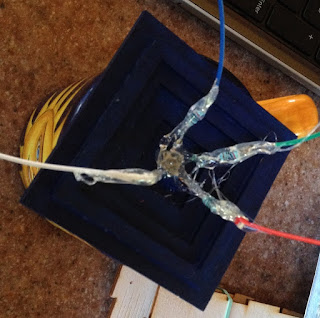
 |
| Electrical components that fit inside the box |
Lessons learned:
I learned that the code for using a common anode RGB LED is slightly different from that using a common cathode RGB. I also figured out how to combine NeoPixel sample code with a blinking RBG LED for really fun effects.
I learned that the code for using a common anode RGB LED is slightly different from that using a common cathode RGB. I also figured out how to combine NeoPixel sample code with a blinking RBG LED for really fun effects.
Breadboarding the entire circuit prior to soldering was essential, and helped to ensure that my code worked. In the process, I was reminded of the importance of burning the bootloader of an ATtiny85 to 8 Mhz before uploading code featuring NeoPixels.
I should have tested the soldering connections with the multimeter as I worked (not after). During my first iteration, I made the mistake of soldering everything to a 1" X 1 " ProtoBoard without noticing that every three holes of the board were connected vertically. As a result, I had to start all over! The board depicted above (which I ended up using in its place) is half of an Adafruit Perma-Proto board, which was more intuitive to work with.
Soldering jumper wires to the LEDs and NeoPixels, and connecting them to wires soldered to the pins of the ATtiny85, is a good way to connect components. Color coding my wires, and using labels, helped to prevent confusion when assembling everything inside of a tight space.
Placing 200 ohm resisters on each of the RGB legs is a good idea.


Using a glue gun to provide strain relief and insulation for the RBG LEDs and NeoPixels is vital.