Sunday, December 31, 2017

Laser-cut Solar Charger

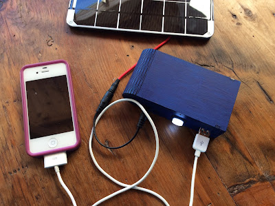
Following Becky Stern's Solar USB Charger Instructable, I just finished making my own portable solar charger!  It hasn't been sunny enough to take the solar panel outside, but I've confirmed that the charger works!

Rather than using a cardboard box for the contents, I used Adobe Illustrator to make a revised version of this simple curved box with a living hinge.  My revision adds holes for the components depicted below.


Completing this project has made me want to learn more about ways that I might apply solar power to future project.


Thursday, September 21, 2017

How to Make a Light-up LED Cuff with a Magnetic Switch #makered

I'm scheduled to teach an e-textiles workshop at the annual Vermont Art Teachers Association (VATA) conference on 29 September.

As part of this hands-on activity, I will be teaching some classroom-tested strategies for helping large groups of students to create their own light-up wearable cuffs, constructed with felt, conductive thread, and ring magnets.

Here is the link to my Light it Up:  Fun with E-Textiles presentation.

If you are interested in learning more, I've also created a new Instructable (and accompanying video tutorial) detailing my process with students grades three through five.  There, you'll find useful circuit diagrams and templates, as well as links to vital supplies.


Thursday, September 7, 2017

Spidery Sparkle Skirt


I sewed this skirt for my daughter last year; but, in the spirit of the Champlain Maker Faire, I just transformed it into a spidery sparkle skirt, using a Flora, an accelerometer, some NeoPixels, and Becky Stern's code.    


Matching pocket to support the battery


Saturday, August 26, 2017

Laser-cut Wood & Leather Purse

I am in the process of learning how to finish laser-cut wood and leather.  I recently finished making a wooden purse for my mother, using an open source design by Scott Austin (CC BY SA).

If you are interested in open source designs, you may want to check out Obrary.com, a fantastic repository for Creative Commons licensed designs that may be produced with a laser cutter or CNC router.


The purse design calls for 1/4" hardwood; as a novice, I started with Baltic birch. While I was excited to get the pieces cut out (especially the living hinge) I learned that I should have modified the design to ensure that the size of the tabs matched up with the exact thickness of my wood.  I also discovered that it's important to pay attention to the direction of the wood grain when moving shapes around in Adobe Illustrator.  Since I didn't consider these things prior to cutting out the pieces, the wood grain lacks consistency and the tab connections look sloppier than I would have liked.

After gluing the purse together and sanding the wood, I used FW Pearlescent Liquid Acrylic Ink, in Birdwing Copper, to add color to the plywood.  Next time, I'll probably opt for a more traditional stain.


While the original purse design had holes for adding hardware and a handle, I had to come up with my own method for creating them.  Rather than ordering something online, I designed a closure and a handle in Inkscape and cut them out with a laser cutter.

After washing the char off of the leather with Murphy's oil soap, and allowing it dry overnight, I painted the leather pieces with Jacquard Neopaque Acrylic Paint in turquoise. After letting them dry, I attached them using double cap steel rivets.  I used E6000 to glue two leather disks to the purse, to serve as a raised button, which the ring slides over when the purse is closed.


By using turquoise and copper, I was trying to create a purse with a southwestern feel (that would match my mom's favorite pair of sandals).  Next time, I'll stick to a more subdued color pallet.

Update:

My next iteration (also Baltic Birch) turned out a little nicer.  The wood grain  is going in the correct direction and the tabs are a better fit.  I used a slightly larger version of the leather closure, which I prefer.  I applied a Minwax Gel Stain to the wood and black Jacquard Neopaque Acrylic paint to the leather.  Next time, I plan to use a higher quality wood.


Monday, August 21, 2017

Second Iteration: Laser Cut Book Cover

This is the second iteration of a laser cut book cover with living hinges.  In my last post, I didn't add holes for a traditional binding, so I ended up screwing in a metal binder mechanism. 

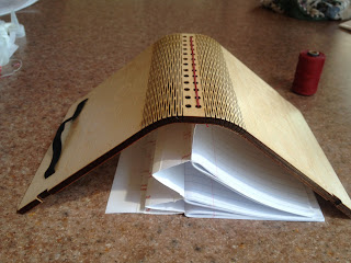
In this latest iteration, I reduced the overall width of the spine and added a flat section with holes for sewing in paper signatures. While the cover remains bulky (it's about 2 inches thick), I made the overall footprint of the book smaller, and added a box around my name.
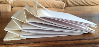
For the spine, I folded a piece of watercolor paper into an
accordion hinge; I reinforced this with double-stick tape and Tyvek from an
old postal envelope.  Since I only had two rows of holes to sew onto, 
I needed to come up with a flexible binding that could expand.
I sewed card stock signatures to the peaks of the accordion.


I sewed the left and right most creases of the hinge to the cover.

I used red waxed linen thread to sew in the accordion hinge.
I had to try this a couple of times, because the first accordion
hinge that I created was too wide and too tall.
Because there is so much room for expansion,
this binding would work well for adding ephemera or
pop-up structures.


I had to trim the height of the signatures so they didn't interfere with the
elastic closure.  In a future iteration, I would paint the watercolor
paper used for the accordion hinge; white is pretty boring.


The cover can fold flat once the accordion hinge is sewn in.


Saturday, August 12, 2017

My First Original Laser Cut Book Cover

This week at the Burlington Generator, I finally figured out how to use Inkscape's living hinge extension to create a laser cut book cover/ photo album.

+Sarah Sutter taught me how to personalize a font by turning text into editable paths. Using what I learned from her during Create Make Learn 2017, I was able to change the spacing and angles of my letters.  I really like the way they turned out.

+Jean Cherouny graciously helped me figure out how to make some improvements in Adobe Illustrator, teaching me how to use the "shift" key to select and edit individual components.  As a result, I was able to change the line widths on all of my circles, to add a little complexity to my design.


Cut from .25" Baltic Birch plywood, the cover (when folded) is 7" X 7" X 2.5".  It's a bit on the bulky side.

After sanding the plywood, I used a clear layer of polyurethane to add a little shine.


I used my sewing machine to secure the edges of the elastic closure.


+April Hallock came up with the idea of adding a metal binder mechanism to the cover.  I ended up harvesting one from an old photo album that I found in a box marked "Free" at the Williston Re-Store.


Right now the 2-ring binder mechanism is attached with nuts and bolts.  While I don't love the way that the bolts look on the back side of the cover (partially due to my lopsided drilling), I'm not yet sure how to add recesses for the bolts; that's something I'm hoping to learn.


Next time, I want to make a book with a smaller, thinner cover and a narrower spine.  In a revised iteration, I plan to add a flat spine with holes for a binding, sandwiched between two living hinges.

Tuesday, August 1, 2017

Laser-Cut Bent Acrylic

I am learning how to design in Inkscape and Adobe Illustrator at the Create Make Learn summer institute!  Today, I made this acrylic iPad/ business card stand using a laser cutter and plexiglass bender!


Sunday, July 23, 2017

ATtiny85 TARDIS

I just finished building this ATtiny85 controlled TARDIS for under $20, using a laser cutter file from this Instructable.   I found printable Police Box decals via a quick Google search.


I modified the Adobe Illustrator file to add a square of 3mm Baltic birch plywood to the inside of the TARDIS top, to keep it from sliding around.  While this slightly improved the original design, it made gluing the NeoPixels to the inside of the box a bit trickier; they needed to be glued a bit lower down on the box than they would have without the added piece.


View of ATtiny85 from underneath TARDIS

I'm excited about this build, featuring 10 hand-soldered NeoPixel LEDs and a diffused 10mm RGB LED, because it led to my further experimentation with electronics.  I've built a couple others incorporating Photons, but this one doesn't require reliable wifi or a pricey microcontroller.

Electrical components that fit inside the box
I am powering the device using a switched battery holder containing 2- AAA batteries. I am still trying to figure out how to use capacitors in order to use a 5V power supply, such as a USB port.

Lessons learned:
I learned that the code for using a common anode RGB LED is slightly different from that using a common cathode RGB.  I also figured out how to combine NeoPixel sample code with a blinking RBG LED for really fun effects.

Breadboarding the entire circuit prior to soldering was essential, and helped to ensure that my code worked. In the process, I was reminded of the importance of burning the bootloader of an ATtiny85 to 8 Mhz before uploading code featuring NeoPixels.

I should have tested the soldering connections with the multimeter as I worked (not after).  During my first iteration, I made the mistake of soldering everything to a 1" X 1 " ProtoBoard without noticing that every three holes of the board were connected vertically.  As a result, I had to start all over!  The board depicted above (which I ended up using in its place) is half of an Adafruit Perma-Proto board, which was more intuitive to work with.

Soldering jumper wires to the LEDs and NeoPixels, and connecting them to wires soldered to the pins of the ATtiny85, is a good way to connect components.  Color coding my wires, and using labels, helped to prevent confusion when assembling everything inside of a tight space.

Placing 200 ohm resisters on each of the RGB legs is a good idea.

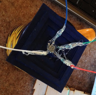
Using a glue gun to provide strain relief and insulation for the RBG LEDs and NeoPixels is vital.

Wednesday, May 24, 2017

Internet Connected CheerLights Hat (Featuring the Particle Photon)

Internet Connected CheerLights Hat (Featuring a Photon)

For more details, CHECK OUT MY INSTRUCTABLE!

This weekend, I whipped up a fun e-Textile hat that combines the magic of CheerLights with a Particle Photon, a microcontroller that can connect to the cloud to help you with all of your Internet of Things projects!  According to CheerLights' Twitter bio, "CheerLights is an #internetofthings project by @scharler to synchronize lights to the same color at the same time all around the world."  If you haven't tried it, you are missing out on something fun- something that has the potential to captivate students who might be wondering how smart objects communicate with the World Wide Web.

The result of my tinkering was an internet-enabled hat that changes colors in sync with lights all over the world, in response to Twitter messages mentioning @CheerLights and the name of a desired color.

If you end up doing something like this with students, you might be also interested in knowing that there's even a free CheerLights Chrome extension in the Google Chrome store, which will allow you to see the most recent color set on the CheerLights Application Programming Interface (API) in an icon on the top right corner of your browser!  This might be useful if you are engaged in prototyping with CheerLights, (or if you're just curious).


I'm sharing the details of my build, in case you'd like to try to make your own CheerLights wearable. I am working under the assumption that you already know how to set up a Photon and upload code using the Particle IDE.  If you don't yet know how to do this, I suggest you visit this Particle Guide.

Useful Tools and Supplies:

1.  a soft fabric hat
2.  a rotary leather punch or Japanese screw punch (to make holes in the hat)
3.  an eyelet setter
4.  eyelets
5.  hammer or mallet
6.  glue gun
7.  soldering iron with helping hands
8.  Photon microcontroller with headers
9.  Spark Fun Photon Wearable Shield
10.  Lily Pad Simple Power
11.  500 mAh Lipo cell battery
12.  10X SMD RGB LED's (or sewable Adafruit NeoPixels)
Note:  NeoPixels are much easier to solder, but the SMD RGB LED's are more compact.
13.  stranded silicon wire (I used red, black, and yellow)
14.  5 male to female jumper wires (2 black, 2 red, 1 yellow)
15.  Velcro squares

Directions:
The firmware/ code I'm using was shared by Matt Holmes in his NeoPixel reindeer project on GitHub. If you are new to the Photon, you might want to spend a little time reading the tips Matt Holmes shares to help you get started with the proper libraries.

1. Upload the CheerLights code to your Photon.  Modify the code so that the PIXEL_PIN is D7 instead of D0 and the PIXEL_COUNT is 12 instead of 1.

#define PIXEL_PIN D7
#define PIXEL_COUNT 12

2.  Solder the male half of a black jumper wire to the ground pin of the Lily Pad Simple Power and the male half of a red jumper wire to the positive pin.

Solder the female half of a black jumper wire to one of the ground pins on the Spark Fun Photon Wearable Shield and the female half of a red jumper wire to the VIN pin on the shield.


3.  Solder the female half of a red jumper wire to the 3Vpin of the Spark Fun Photon Wearable Shield. Solder the female half of a yellow jumper wire to the D7 pin.  Solder half of a male black (I used brown) jumper wire to the other ground pin.   Insert the jumper wires attached to the Lily Pad Simple Power into their corresponding male jumper wires on the Spark Fun Photon Wearable Shield.

4.  Find an old hat that could use a makeover.
(Black felt is flexible enough to roll and bend, making it easy to poke holes with the leather punch).


5.  Select an eyelet setter.  A universal eyelet setter may be easier to use than the squeezable type if you plan to place eyelets far from the hat's brim.


6.  Use the leather rotary punch or Japanese screw punch to create holes in your hat that are slightly smaller than the eyelets you're using.  Set the eyelets so that the finished sides are visible from the front of the hat and the rough edges are on the inside.

I've got a piece of granite under my hat to protect my work surface.

7.  Use a glue gun to protect the solder joints.  You can Velcro the shield, Lily Pad Simple Power, and the battery to the hat now or later.


8.  Solder the SMD RGB LED's (or Adafruit NeoPixels) together with stranded wire, ensuring that the wire is long enough to reach each of the holes that you made.  I used black wire for ground, red for power, and yellow for the data lines.

I cut and tinned the data wires before soldering the strand together.  I used a set of third hands to secure the notched corner (ground) as I worked.

 If you're using SMD RGB LED's, take note that one corner has a notch in it which denotes ground.  Use the ground notch to ensure that all of your LED's are oriented properly as you work.


9.  When you're finished soldering the lights, solder the female halves of the red, black, and yellow jumper wires to the matching wires attached to your light strand.

Verify that the data in is positioned at the top of the strand.


Switch on the power to the Lily Pad Simple Power.


Once your Photon connects with the Internet, you should be able test your test your light strand. After ensuring that all of your LED's are working properly, protect the solder joints with hot glue.
Protect the solder joints with heat shrink wrap or electrical tape.


10.  Insert the female jumper wires attached to the light strand into their corresponding male jumper wires on the Spark Fun Photon Wearable Shield


11.  Switch on the power to the Lily Pad Simple Power.  Once your Photon connects with the Internet, you should be able test your test your RBG LED/ NeoPixel strand.


12.  After ensuring that all of your LED's  are working properly, protect the solder joints with hot glue.


13.  Glue your LED's into position, centering them within the eyelets before the glue cools.  I found it helpful to detach the Spark Fun Photon Wearable ShieldLily Pad Simple Power, and the battery first. I began by gluing the last light in the strand, working my way towards the microcontroller.


14.  Enjoy your awesome new internet-connected creation!


Matt Holmes, you are a true hero for sharing your code (and your reindeer project) with the world! THANK YOU.